by Shaun Nielsen
Five years ago a very lucky owner of a beautiful, iconic Ducati 996SPS loved to pull wheelies. Long, sustained wheelies. The kind that gives all the oil in the sump time to pool in the back of the engine – a long way from the oil pump pickup…
As a result, the plain bearing shells in the connecting rods ran dry. Metal to metal contact took place and at many thousands of RPM, this generates a lot of heat – enough to melt the steel in the bearings, welding them to both the crankshaft and the connecting rods. At high RPM this makes a huge mess. Metal is torn to shreds and carried throughout the engine. The oil pump picks up shards and as a result the pump is damaged, sometimes destroyed. If the metal fragments make it into the transmission, even more damage. And if the cams get contaminated, the destruction is total.
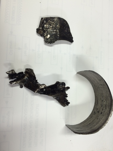
All three of these chunks should look like a half circle!
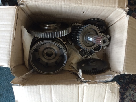
That’s the situation I faced when I had a dozen boxes delivered to the shop. Inside were the dirty and dusty engine innards, stripped by an unknown mechanic with absolutely no concern for order or details. Some damaged parts were in a baggie, complete with scorched oil residue, loose ball bearings and spider eggs. What fun guessing which is which…
Many parts were missing, and what was left was piled in random boxes along with a collection of parts from several other, unknown bikes.
The clutch was destroyed, not by the wheelie incident but by obvious and brutal long term abuse. And while the bottom end was in gruesome condition, the cylinder heads were almost unscathed. Only one rocker was suffering from a flaked chrome surface (known to plague the entire 996 range) and the cams were pristine. Thank heaven for small mercies, as these are exotic SPS cams that cost upwards of $1000 each – if they can be found at all!
That left me looking at the chassis. The frame and fairing looked pristine on initial inspection. It wasn’t until later I found repaired crash damage, along with some damage that couldn’t be repaired.
I started the long repair process with the crank and connecting rods. Being an SPS, the rods are Pankl titanium items, and as a result the crank is a totally different shape to account for the much lower reciprocating weight.
When the new crank and rods arrived, the process of fitting it to the original crankcases began. Ducati is not like Japanese brands, there is enough variation in manufacturing tolerances to require the crank and transmission shafts to be shimmed to fit the cases.
I stripped the transmission shafts and removed shards of steel and lead bearing material. Of little surprise was the fact that the main case ball bearings were full of metal flakes. I tried cleaning these but no matter how long they spent in the ultrasonic bath they always felt ‘gritty’. No option but full replacement of all six.
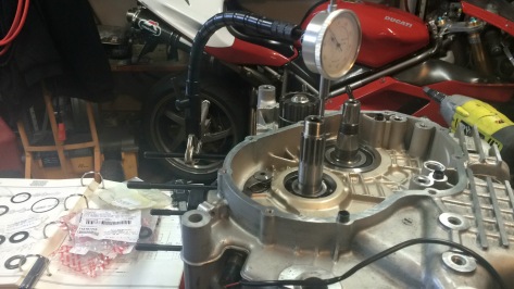
With new bearings it was time to fit the transmission shafts and crank to the cases with the correct tolerances (0.5mm, 0.5mm and 0mm respectively) . With all new bearings, perfectly fitted shims and nice clean transmission gears in place, it was time to assemble the case halves.
While bolting the cases together I had to think long and hard about how much sealant to use on the mating surfaces. Having recently stripped a similar motor I was shocked to see how much RTV material was floating around in the sump. The oil pickup screen was covered in the stuff, and this was from the factory!
Is it better to use too much to guarantee no stains on the driveway and risk blocking a piston cooling jet? Or is it better to use as little as possible to ensure no blobs of liquid rubber find their way to the wrong place, but risk an occasional drip?
This is the eternal question. And as a result I think I followed the fine line between sealing the oil in and keeping the RTV out.
(One lesson I learned the hard way though many years ago – once the cases are bolted together, keep them horizontal long enough for the RTV to harden before tipping the cases up. Oil, or WD-40, that mixes with uncured RTV is an almost guaranteed leak.
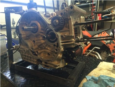
After leaving the assembly overnight to cure, I set the engine in its freshly welded up engine stand. This is where the fun really began. I installed a bunch of new seals and o-rings. The timing gear for the desmo drive went in, then an assortment of primary drive and clutch gears with new woodruff keys to replace the missing pieces. New lock washers kept the gear nuts in place.
I had to source a new oil pump as the original was damaged when it picked up chunks of bearing shell. The new pump went in easily.
With the primary gears, clutch and starter gears in place, the side covers went on. New gaskets and seals will hopefully keep all fluids in their proper place. Having done only a few more than 20,000 miles the coolant pump was in good shape and the steel coolant pipes had very little corrosion. Next step is to prep the chassis for engine installation.
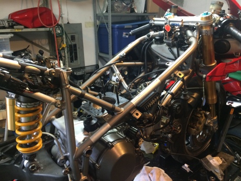
With the chassis on the table the engine went into place quickly and easily.
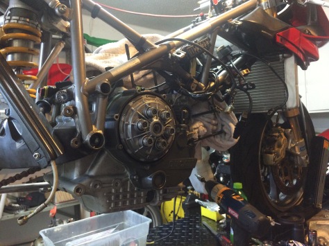
One fascinating thing about the Desmoquattro is the dry clutch. For a few percent more engine output, Ducati separate the clutch from the engine oil. This has a few interesting side effects. The first is the constant clanging and rattling. The clutch plates rattle against the clutch basket to the point where people ask ‘Whats wrong with your bike?’
Another interesting side effect is the ability to run regular oil in the engine. Motorcycle clutches usually run inside the crankcases in a bath of oil. As a result, as the clutch wears the oil carries away the organic particles but without being so slippery as to cause the clutch to slip. In a Ducati the clutch rattles away outside the engine. This means the engine can use the same oil as a car, making it much easier (and cheaper) to do an oil change. Research showed a huge variety of opinions on what oil to run. Some say a light 10w40 is best because thats what the manufacturers recommend. However, their primary focus is milage so they will ignore factors like shear strength and oil film retention, critical issues for an engine with 2 large pistons moving much faster than similar sized pistons in a car engine.
Experience from a builder of Ducati race engines and his interactions with oil analysis firms prompted me to go with a mineral 20W50 grade oil. This prevents oil film breakdown inside the main bearings and also ensures a protective film stays on the engine components after shut down. The downside is that this oil demands a careful warmup period before the engine is put under stress. With a future of occasional trackdays this procedure will be easy to stick to.
As you can see from the picture, the engine looks a little weird without cylinders. While I was waiting for parts to arrive I sifted through the boxes to find all the parts of the cylinder heads. This is the part of the engine that makes a Ducati truly unique, and significantly more complicated than the average Japanese motorcycle engine.
Desmodromic valve actuation is the process where one cam pushes the intake valve down to allow air in, and another cam pushes the valve back up again .A Japanese engine relies on a simple spring to close the valve.
Keeping complete control over valve motion like this makes a lot of sense. The energy required to compress a valve spring when opening all 16 valves is instead sent to the rear wheel. And when you consider that each valve spring has to be strong enough to force a valve closed at high RPM, thats a lot of engine power not devoted to forward motion. The average sprung valve requires one cam lobe and one shim to adjust the valve clearance, which is the open space between the cam and the top of the valve stem. This is typically free space to allow thermal expansion of the valve as the engine heats up. The average valve also has a tendency of hammering itself up into the cylinder head, closing this gap. This happens when an aggressive cam profile, or poorly adjusted lash, allows the valve to slam into the valve seat – a hardened steel ring pressed into the soft aluminum combustion chamber.
Consider that under normal operation the valve will contact this seat 10,000 times a minute. The issue here is that its critical the exhaust valves do come into contact with their seats each cycle. As hot exhaust gas flows past the valve, it absorbs some of the intense heat in the gas. The only way to get rid of this heat is when the valve touches the seat. A short distance behind the valve seats of the average modern sportbike is a channel carrying fast moving liquid coolant. This coolant carries away the heat just transmitted to the seat. However, if the valve lash is left unchecked it can close up to nothing, so as the valve stem gets hot and grows, the valve stem will rest against the cam and not touch the valve seat and never get a chance to pass the heat to the coolant. When this happens, results are often bad. The high strength valve material gets so hot it loses the properties that made it a good valve. And if the valve head were to snap off, well you can imagine the carnage.
So, Ducati have gone to extreme lengths to prevent this from happening. By having a cam dedicated to closing the valve we never have to worry about troublesome issues like valve float or harmful resonant spring harmonics (a common result of poorly planned or understood engine modifications). The minor issue of lash can be dealt with easily enough. The benefits of this desmo drive can be felt as soon as you try rotating a Ducati crankshaft by hand and then comparing this to the effort required to rotate the crank of even a much smaller capacity Japanese engine. With no valve springs fighting against the rotation, the Desmo crank turns smoothly and easily. Consider this reduced effort at 10,000 RPM and the benefit of Desmo drive becomes apparent.
But now for the downside. Having twice the number of cam lobes and their requisite rockers and actuators can make for a complex cylinder head. And of course each valve operation requires its own lash adjuster shim. This means a Ducati V-twin engine has sixteen shims that all need to be checked and adjusted on a surprisingly frequent basis. Compared to a Japanese engine this can be a little frightening. Its one of the main reasons Ducatis are expensive to own – the skills required to adjust these valves is typically quite expensive. And that’s before the cost of parts is added to the mix.
For this engine, I had the luxury of time and access. I assembled the cylinder heads and all their rockers and actuators and all the little shims. Measuring in tenths and hundredths of a millimeter I was able to establish which shims were required to keep the valves where they were needed and when. Its a complex procedure, but not a difficult one. With the right measuring tools and a supply of shims it takes a few hours per cylinder – when the head is off the engine. Its significantly more difficult to do with the head on the engine, but I’d rather not think about that…
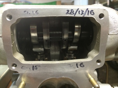
With the heads already fully assembled and accurately adjusted it was a simple matter to install new rings on a set of used but immaculate pistons. I had also found a set of cylinders that, when measured, showed less than 0.01mm of wear from new. New rings went onto the pistons. The pistons went into the cylinders, and the pistons were then connected to the beautiful titanium Pankl rods.
With new gaskets, the heads went on.
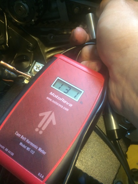
Next up was a particularly fun job, adjusting the tension of the toothed belts used instead of cam chains. This is a critical adjustment on the Ducati. With no valve springs to pull the valves out of the combustion chamber, a broken belt can be catastrophic. To prevent this, the belts must be accurately tensioned, and kept there. The factory recommends a frequency tensioning method. This is tested by plucking the belt like a guitar string while holding a microphone close by. This microphone is connected to a digital device which measures the tone generated by the vibrating belt. The proper tension will generate a tone in the 110 Hertz range.
The first time I used this tool I was getting wildly varying results which I couldn’t understand until I realized the light fixture right above my work table was loud enough to interfere with the belt tone. Once I turned it off I got a reliable readout every time. It was the wrong readout, but at least it was repeatable! By reducing the tension I was able to tune the belts easily and accurately. It was an expensive tool and after I sold my first Desmoquattro I was tempted to sell it also, until I remembered the old axiom – NEVER SELL TOOLS! Sure enough, I’ve used this tool many times since then. It’s paid for itself many times over.
Now that the belts are done, its time for electrical connections.
One thing that I appreciate about Japanese bikes is their consideration when it comes to wiring. A CBR1000, for example, has a dozen or so plugs to connect but every one of them is different enough to prevent a mix up. Not so with Ducati… I had to peel back the waterproof jackets on two identical plugs that came out of the main harness side by side. By looking at the wiring diagram I could see what these connections were, but this took time. A smart(er) engineer would use a plug for one connection and a socket for the other. In this way there’s no question and no delay in working out which plug goes where.
The connections involved were the RPM sensor and the crank angle sensor, two inputs required by the fuel injection computer. While doing some research on the SPS injection system, I was surprised to learn that the SPS is one of only three engines in the desmoquattro range that had an individual fuel injection map for each cylinder.(the 748R, 916SPS and this 996SPS)
Going back to the original Desmoquattro, the 748 racer of 1986, the production 748, 916 and 996, each engine used one map that was a compromise of settings for each cylinder, and was almost always wrong for both.
For the SPS though, the P8 computer has enough memory and processing power to store a unique list of injector durations for each cylinder. This means that a preset list of numbers is saved in memory like a spreadsheet so that at a certain RPM and throttle opening, the injectors will be turned on for a specified time when the crank reaches a certain position. Considering that the front cylinder receives a lot more cooling airflow than the rear cylinder, the rear benefits from a touch more fuel to provide a cooling effect.
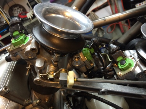
Additionally, I learned that the twin injectors in the standard 996 motor are used in parallel to provide enough fuel flow at high RPM (considering the very short amount of time the intake valve is open). But this can cause problems at low RPM. If both injectors are hard wired together, at low RPM they can actually squirt too much fuel into each cylinder which will cause a rich condition and a rough idle.
With the SPS though, the computer maintains a smooth idle by cutting back to a single injector at low rpm, then when a single injector can’t squirt enough fuel into the cylinder, for example during the 10 milliseconds available at 12,000 rpm, the computer sends a signal to both injectors to open for half the time required for one.
This may be rudimentary stuff for todays modern sportbikes and their high powered, 64-bit processors, but the Desmoquattro was designed to use cutting edge technology – in 1986!
A drawback of this older (some might say ancient) technology is the limited number of parameters available for the injectors. The computer in the SPS only has room for 256 values in the injection table, or map. At any given engine RPM, the computer picks a duration to open the injector/s based on how much twist the rider is giving the throttle. This duration is then modified based on input from sensors checking ambient air temperature and pressure and coolant temperature. The result is a relatively accurate fuel/air mixture fed to the pistons in almost all conditions – when compared to carburettors!
Modern fuel injection is much more sophisticated but works on basically the same parameters. (We’ll discuss ride-by-wire, virtual powerbands, and throttle scheduling next time…)
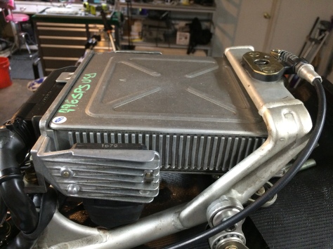
An interesting point worth mentioning is this banjo fitting installed on the outlet of the oil cooler.
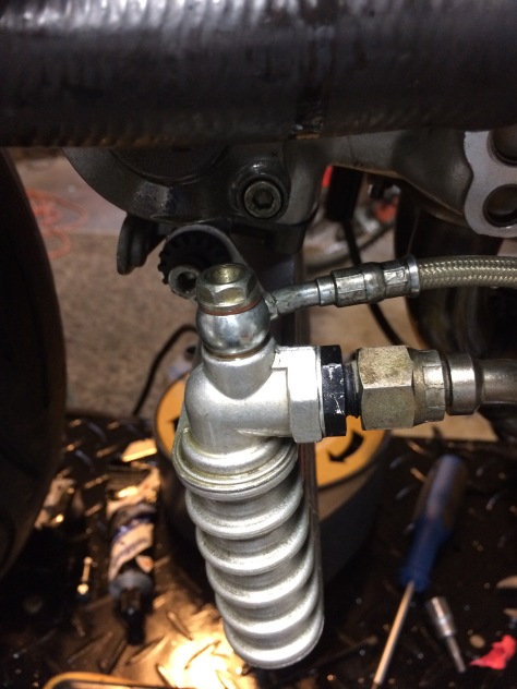
Apparently, the predecessor to the 916 had terrible problems with their cams and followers burning up due to lack of lubrication. A simple solution – pump oil straight from the cooler to the cams. This braided hose carries oil directly from the point where the oil is at its lowest temperature, to the point where its needed most. This contributed to the service intervals on the 916 being much longer than the 851/888 because the parts most susceptible to wear had a constant supply of clean, cooled oil.
Stay tuned for more build details. As soon as I get the last of the coolant hoses the EFI tuning will begin. And when the mirrors and indicators arrive the bike will be ready to deliver to the very patient owner.
